- Synthtopia
- 10 thoughts on “ Getting Started Making DIY Eurorack Modules ”
- SyntherJack
- DIY sound synthesizers and me.
- Eurorack module DIY tutorial (4) – wiring
- Before the wiring…
- Wiring!
- Trigger LED holder
- Finishing touches
- One thought on “ Eurorack module DIY tutorial (4) – wiring ”
- Модуль eurorack своими руками
Synthtopia
The latest episode of the Modular Monthly video series takes a look at getting started making DIY Eurorack modules.
The video takes a look at getting started with synth DIY and making the Music Thing Modular’s Radio Music module.
Are you making DIY Euro modules? If so, let us know how you get started and if you’ve got projects that you’d recommend!
Resources:
- Thonk – UK Euro synth DIY resource
- Synthrotek – another Euro synth DIY resource
- Music Thing Modular
- Synth DIY on Synthtopia
10 thoughts on “ Getting Started Making DIY Eurorack Modules ”
I jumped into DIY with no experience whatsoever. My first Euro module was L-1 basic VCO. Surprisngly it didn’t explode when I powered it up. After that I assembled Random*Source Serge VCFQ, Grayscale Algorhythm and Binary (Binary is pretty tough, lots of SMD), L-1 Quad VCA and couple other modules. It feels really good to solder stuff once in a while.
From time to time I build stuff. Mostly on strip-board. Assembling kits is also fun, but I wouldn’t cal the DIY in any strict sense of the word. But it is certainly a good way to stay off the streets and get your hands on some of the stuff that you cannot buy pre-assembled. Soldering is a vital skill for anyone working with electronics. Even if you just fix loose contacts on cables once in a while or add a component or two to a machine you already have, it’s highly recommended that you learn your way around a soldering iron and those kits can be a great way to do that. At least that’s part of how I started, not with synthesizer kits, they sadly didn’t exist back then.
my first DIY build was a pair of 4MS P.E.G. .. slow and steady is the rule
a good learning experience .. but i would just buy a assembled and tested unit if i had to do it again
Got into the whole DIY thing through repairing/restoring old analog Soviet junk. First Euro module was the random*source Serge VCFQ, which I’m totally in love with! Planning on doing more DIY euro stuff, as I have my eye on a few more r*s modules.
Soldering pcb’s……ummmmm
if your my age (57) buy a jewelers loupe / magnifying glass
then you can not only see the bloody tiny bits
but you can check if your any good at gluing them in the right place properly
great video! only took a few minutes of watching before I went and ordered the Radio Music kit.
I’ve tipped Synthopia many times on my DIY chips but Mr. Synthhead doesn’t seem to care.
When ever I got something featured it has been by Guest, whoever that might be.
Anyways my chips are really cool and very DIY friendly.
For instance the K5 additive oscillator chip.
“I’ve tipped Synthopia many times on my DIY chips but Mr. Synthhead doesn’t seem to care.”
Jan – we care about covering news of interest and use to our readers and not wasting their time with incomplete or misleading information.
We’ve covered your products many times – here are three recent examples:
However – as we’ve discussed with you privately, via both email and Facebook messages – you regularly request coverage of your products, but provide information that is incomplete, is incorrect or misleading, and is lacking an audio or video demo.
If you want to be covered by Synthtopia, our readers expect:
Accurate and complete information about the product;
Pricing and availability details;
Audio or video demos for products that make sounds;
Complete documentation and usage examples for DIY products; and
Accurate information about licensing (open source, CC) where appropriate.
Deal with others professionally, Jan, and they will give you the same respect.
PS: The URL you provided for your site is incorrect. Here’s the correct URL, for readers that may be interested:
While it’s true that there has been a lack of demo videos it’s not true that anything has been incomplete, incorrect or misleading?
Источник
SyntherJack
DIY sound synthesizers and me.
Eurorack module DIY tutorial (4) – wiring
Lets go to the last part of our eurorack DIY. The PCB is designed and tested, front panel with decal and PCB holder made. The last thing is to electrically connect PCB with all panel mounted devices. There is a lot of place for mistakes, so I recommend to work slowly and stick to the schematics (or wiring plans).
Before the wiring…
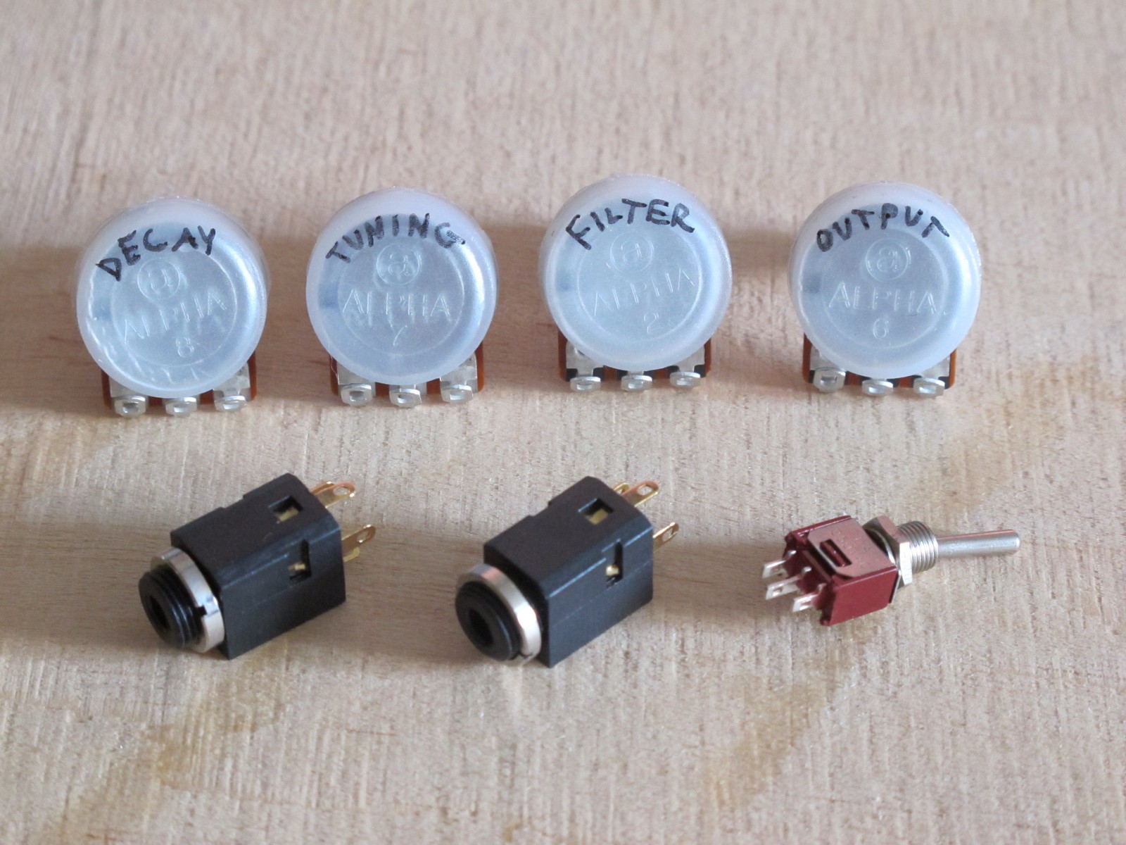
… get all panel mounted devices, check its values and mark their function. There is nothing worst then launching your vanilla module and thinking: “The resonance pot works strange. Do I really used 50k reverse log?”. This way you have one problem less.
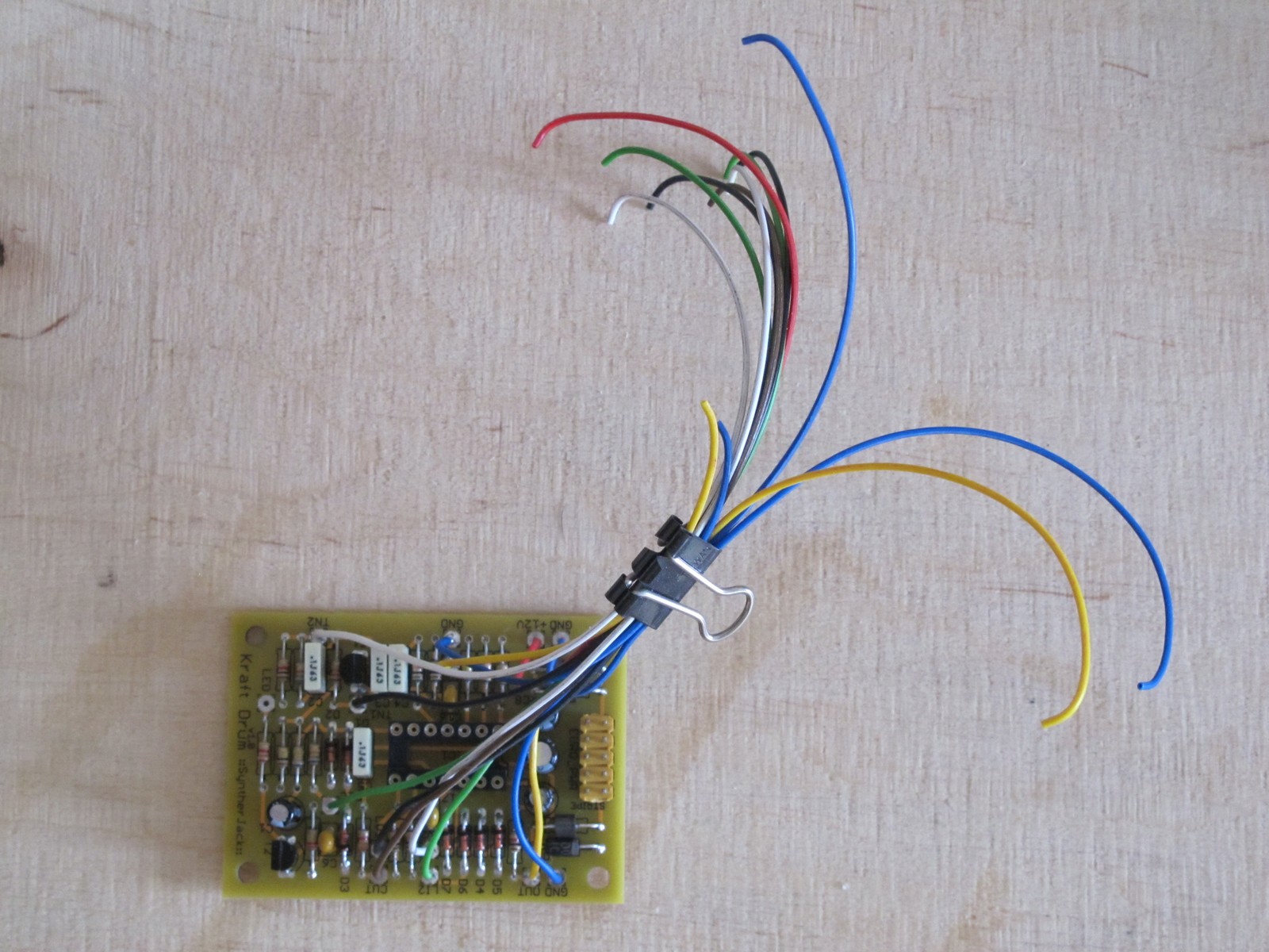
Put the PCB to the mounted PCB holder and check the approximate distance between farthest panel element and PCB wire pad, then add 50 mm. For front panel wiring I usually use 200 – 250 mm wires and then cut / strip them if necessary.
To avoid errors (and speed up debugging) I use simple rules:
- blue wire is always GND,
- red wire is always +V; (-V is not very common on the front panel and I don’t want to waste a specific color),
- yellow wire is input or output signal, i.e. all audio and CVs connected to jacks,
- grouped connections (f.e. to one, 3 terminal potentiometer) must use clearly different colors, f.e. black, white, green (not many colors left) – this way you can track them easly, as the common mistake includes switching center and side terminal.
To keep wires tidy while front panel wiring, I simply use office paper clip and take only the wire I need.
Printed circuit board to holder fixing pack – 10 mm screws, nuts, spring washers (plain will work too) and 2 mm plastic spacers (to ensure the PCB solder side will do not touch the conducting aluminum sheet).
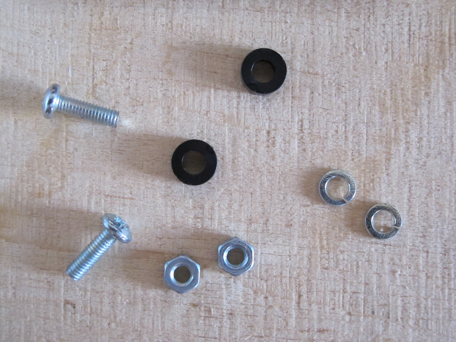
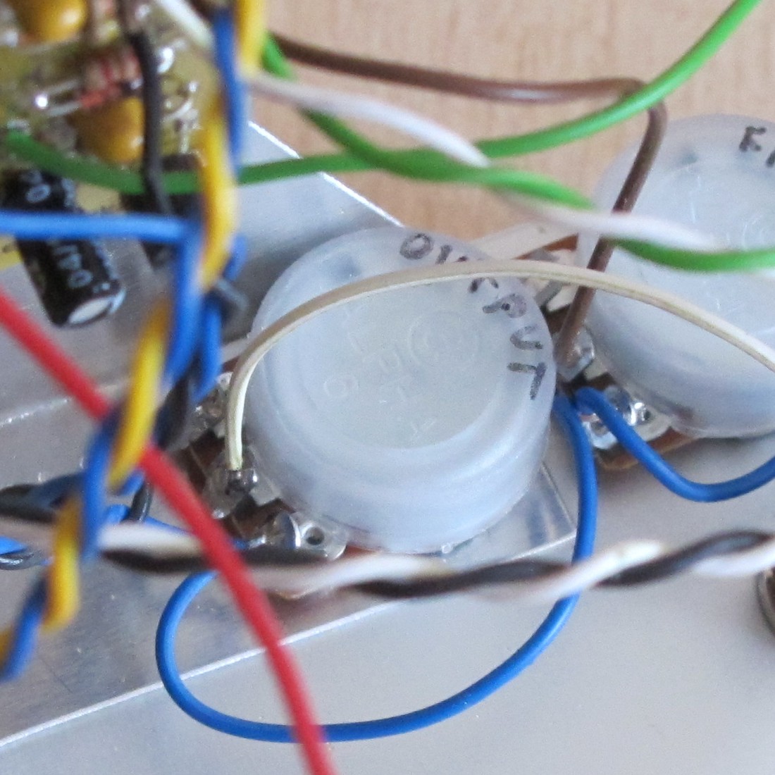
Now we need to put everything together. Unfortunately all pots are 17 mm in diameter (16 mm + 1 mm of anti-dust plastic cover) and there is really tight. To be able to solder DECAY pot (the one on the top left), I didn’t mounted FILTER pot (it should go between DECAY and OUTPUT) to have a free way to DECAY pot terminals. This is no problem for TUNING (switch below it is small) and OUTPUT potentiometers (a lot of place below it, but can also be rotated for better access).
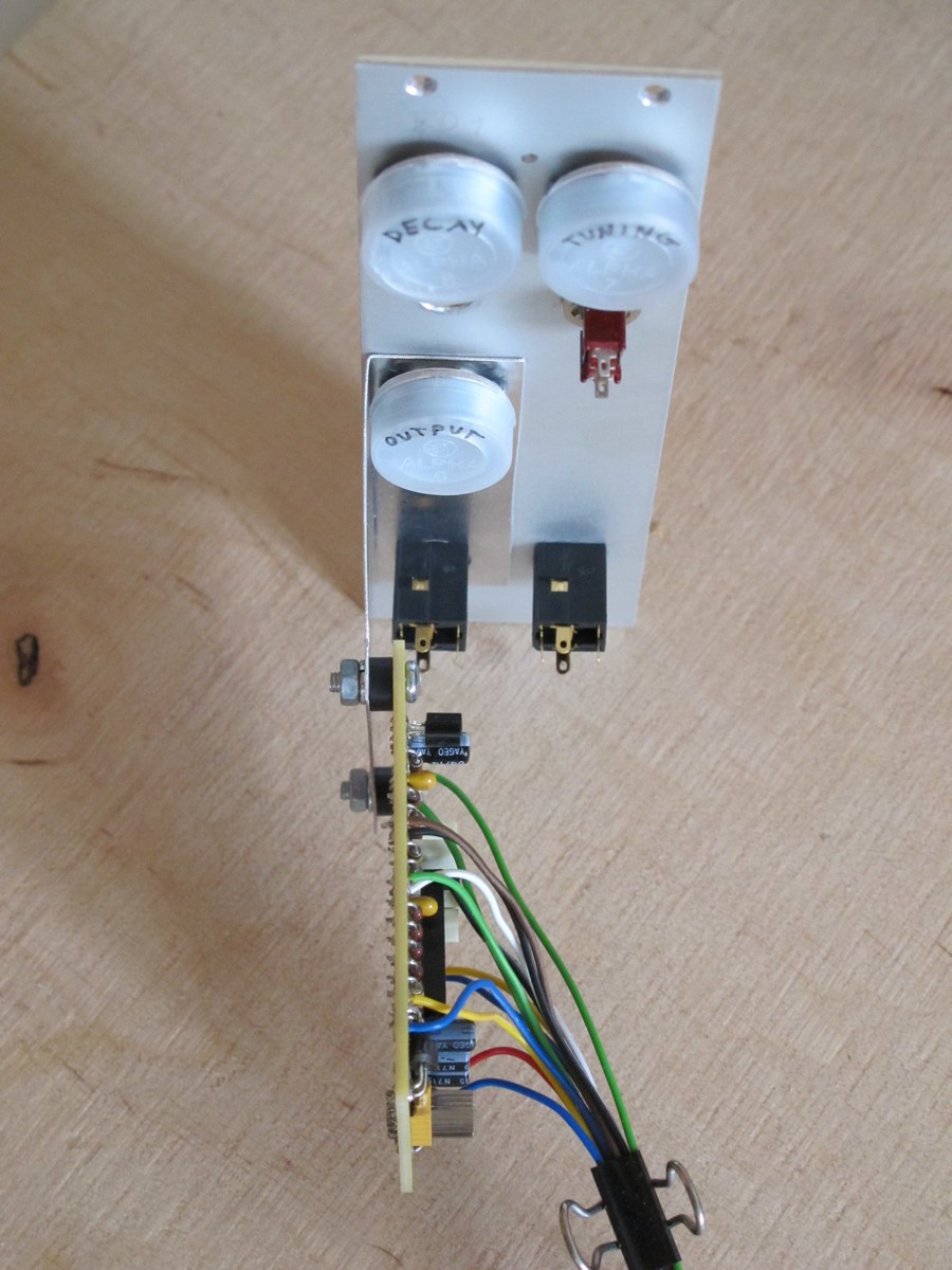
Wiring!
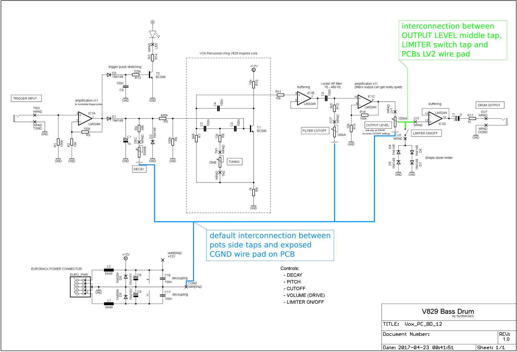
Now we are ready to wire out module! There are only 2 jacks, 4 pots and a switch – quite easy task. Also 2 interconnections on the front panel. There is no additional wiring diagram, so you need to read everything from the schematic. Because the panel mounted elements are outside the PCB, their connections are sometimes marked in a strange ways on the schematic. Generally you are looking for the connections between two front panel parts (potentiometer / jack / switch / LED) – sometimes shown in a direct way ( green ) or as default connection via power lines symbols (ground, V+ etc, marked on the schematics with blue ).
The rest on the connections is straightforward – just some front panel mounted component terminal to PCB wire pad. I always use small jack socket description sheet I made few years ago to not switch the connections accidentally.
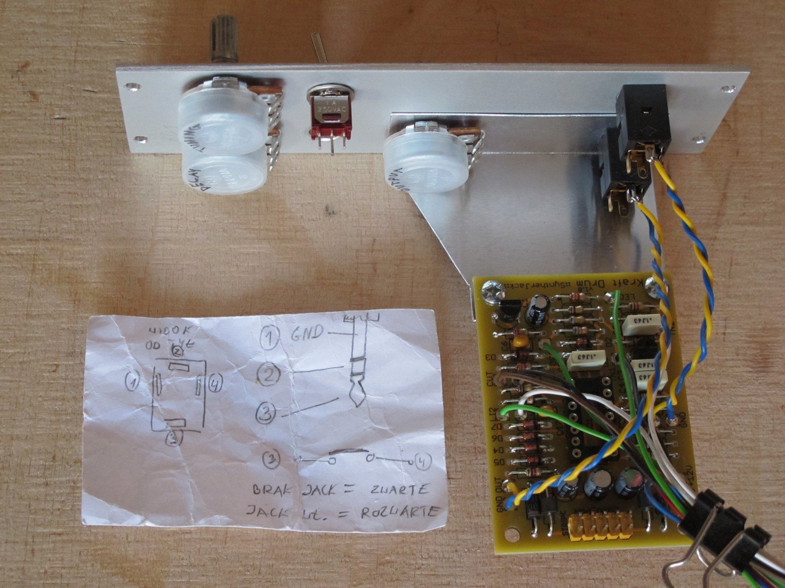
First I soldered the jacks wires, then the OUTPUT pot. Moving in one direction is handy, because there is always enough space for soldering iron. Then I soldered a green wire to DECAY pot, but noticed, there is also a blue GND that needs to go thru the FILTER pot (so I had to install it anyway). Wiring itself is almost pure improvisation 🙂
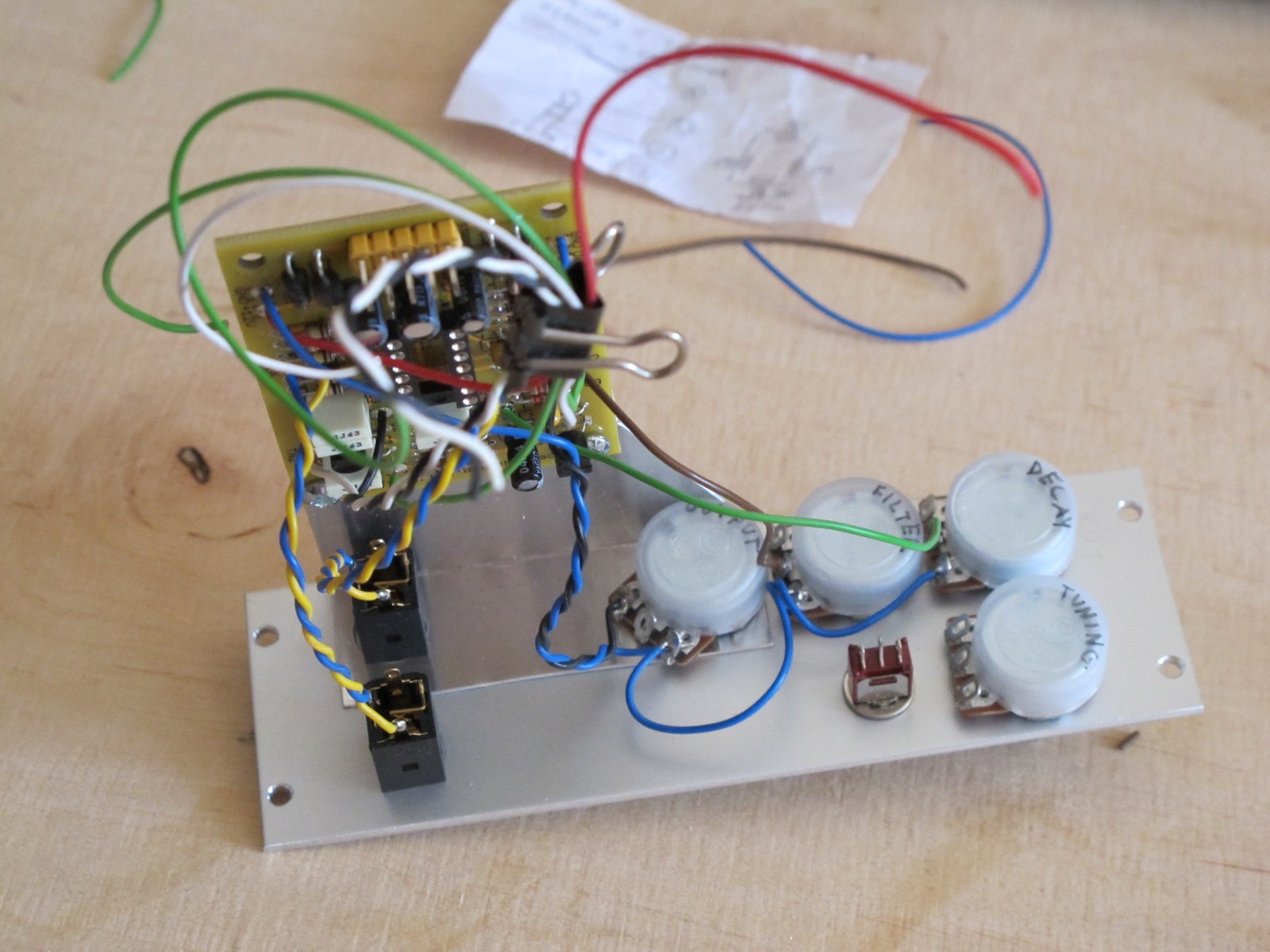
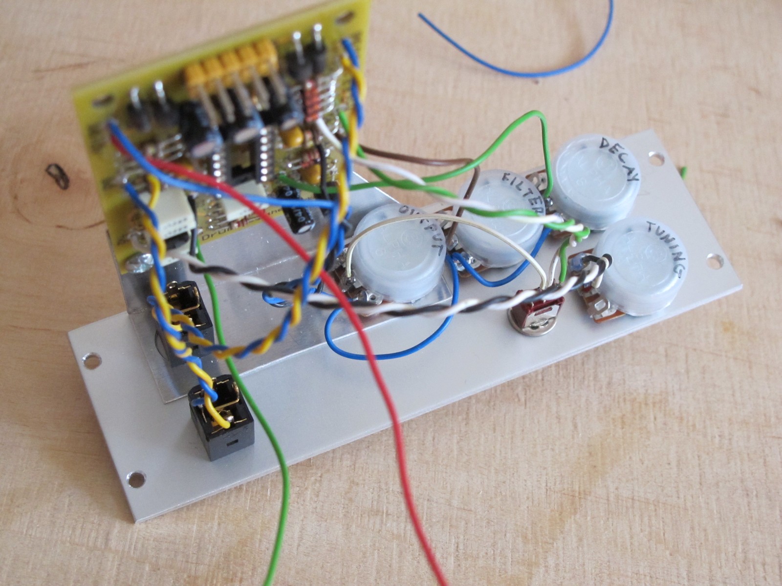
Trigger LED holder
The one thing is missing – trigger LED. It is sqeezed between DECAY and TUNING potentiometer and it needs a little effort to fix it. The way I usually use is to add a small universal PCB and glue it to back of the pots with double sided sticky tape (or just hot-melt adhesive). This way you can disassemble LED later.
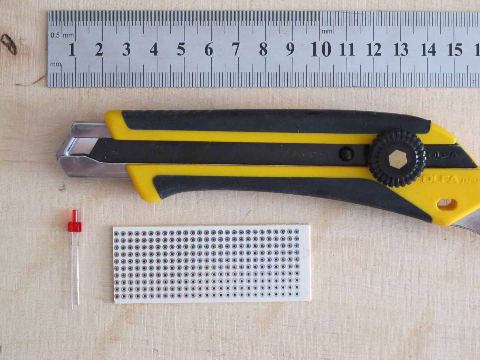
Lets prepare a LED holder with basic tools. For PCB cut I always use a sharp segment knife (Olfa L-5 (
10 euro) with Black Series blades) and a steel ruler. Just few straight cuts from both sides and you can break every PCB with ease.
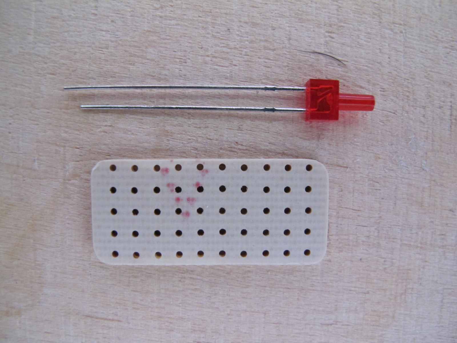
First I put the LED into the front panels hole, then slided a PCB onto it and soldered. This way the position of the LED will be perfect, but you have to be careful not to break throught waterslide decal!
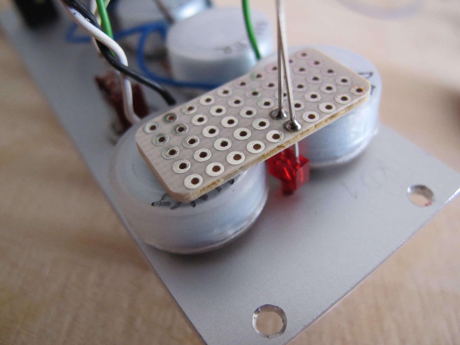
Now mark the LEDs GND (usually* the shorter terminal), cut the both legs and bend them into loops – it makes wire soldering more easy.
*once had a small adventure with SMD LEDs. According to datasheet, the anode is marked with green stripe and I placed them like that. I finished with almost 40 LEDs soldered backwards 🙁 Now I check every LED I solder with a tester.
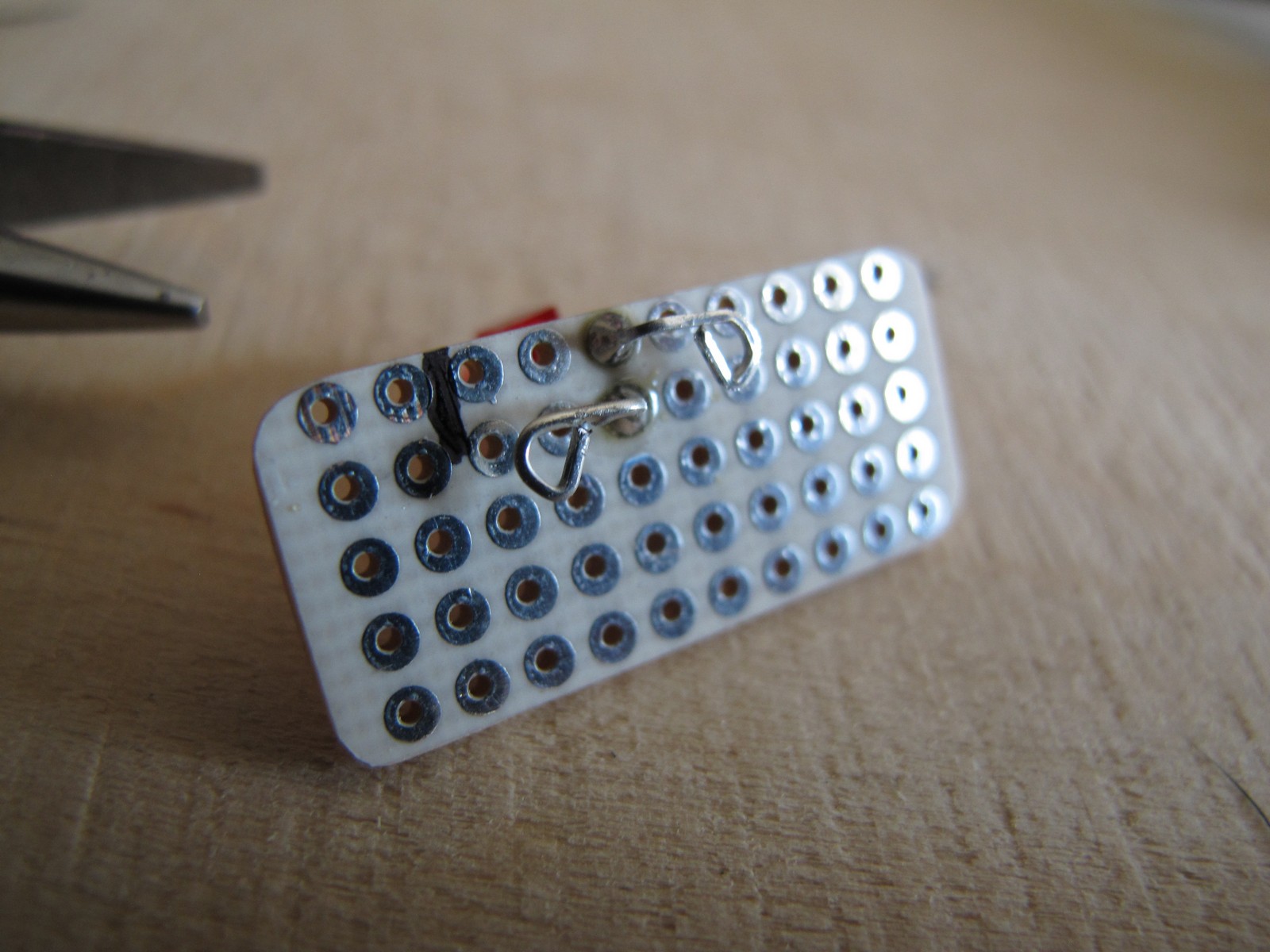
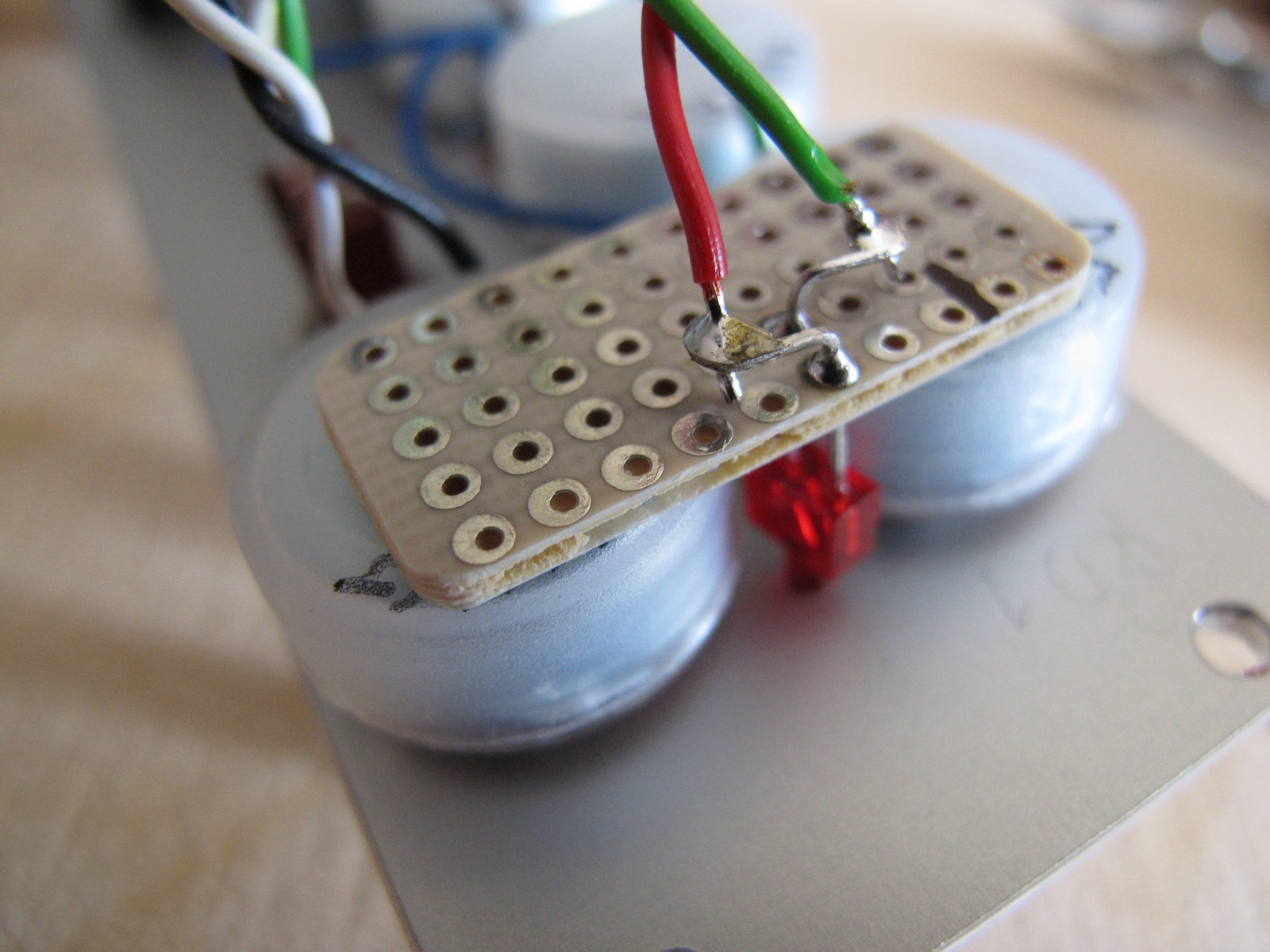
The last thing – solder the LED and glue PCB to the pots (or not, if LED holds on by itself). According to schematics, the anode goes to +V ( red wire), and cathode to transistors collector via resistor.
Finishing touches
All the wires are connected. It is a good time to check them once again (I love checking things!). Look at the potentiometer teminals, maybe two of them are shorted (happens quite often).
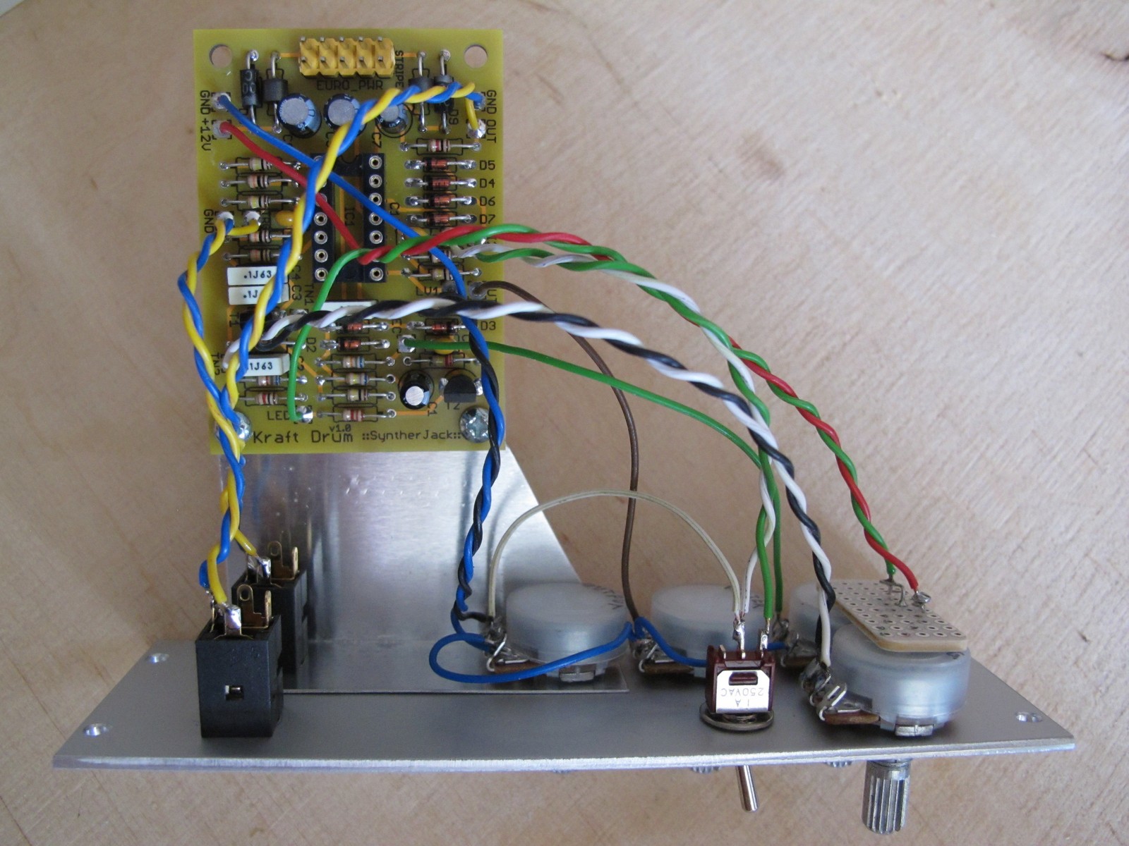
And the last last thing – zip the wires to make your module look even more pro. You can also put potentiometer knobs. I use 10 mm aluminum plated GSL10 type, they have great price/look ratio. Only 0,3 euro per piece.
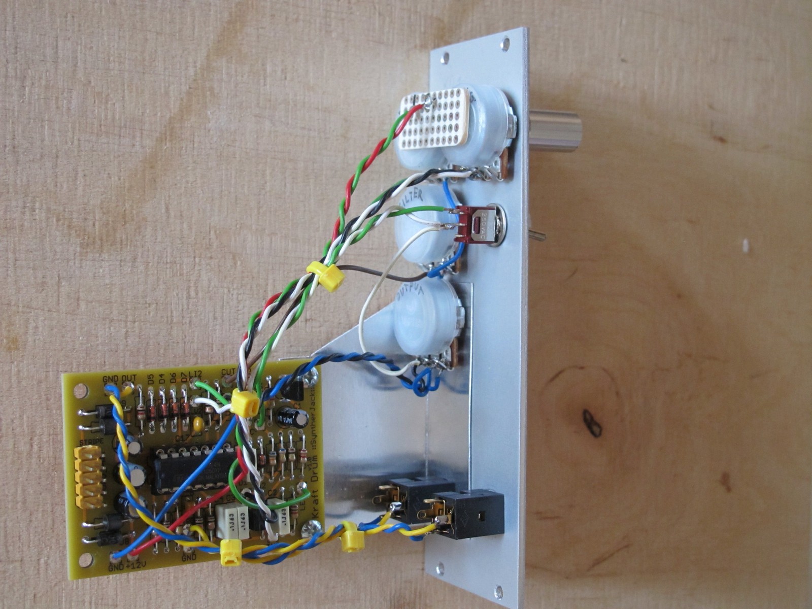
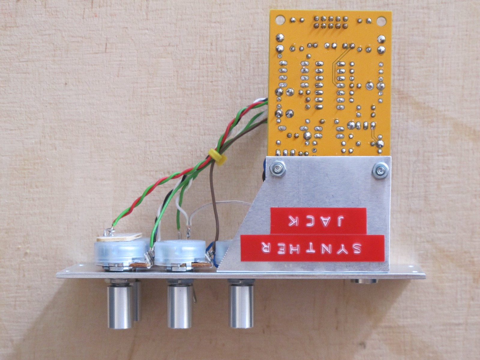
The access to solder side of the PCB is easy in case you want to make troubleshotinge of the module or just modify it.
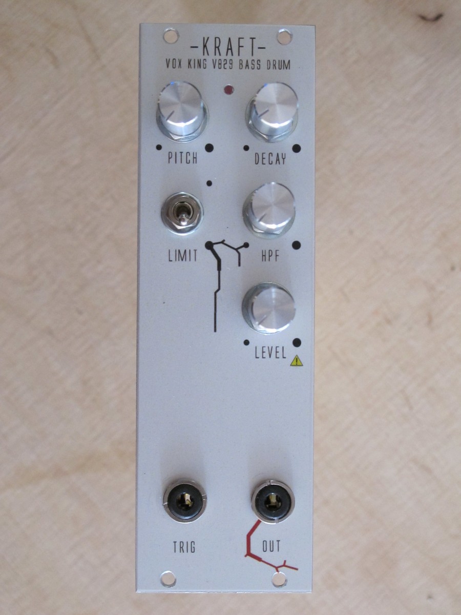
The module is ready!
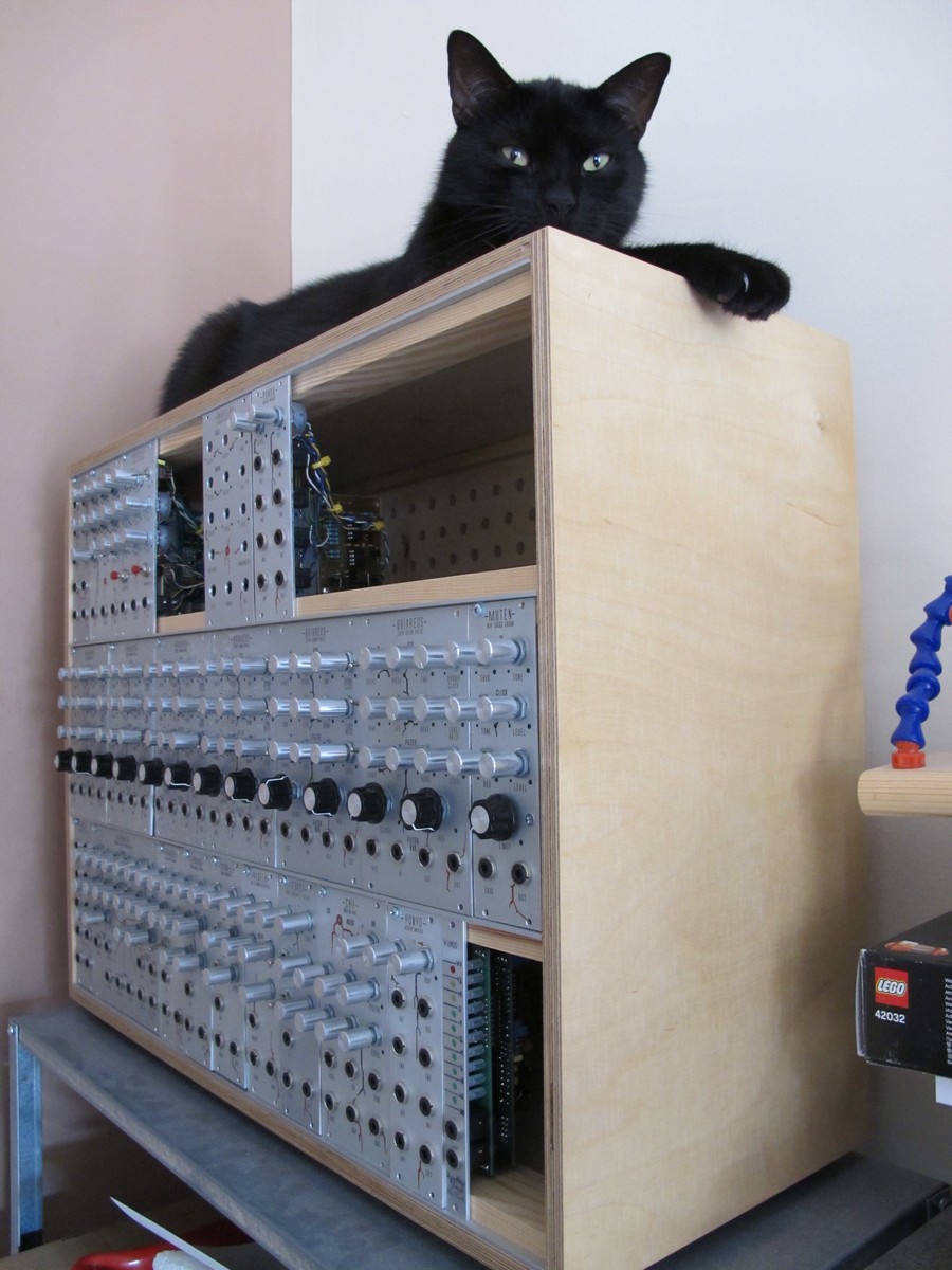
I wouldn’t say it is build like a tank, but almost all of my modules survived a 2 meter drop tests performed by my cat (named Totoro).
Now you should go and make some electrical tests, but it is another story…
One thought on “ Eurorack module DIY tutorial (4) – wiring ”
great tut on wiring, im about to do something similar, and i cannot stand no more using random gauge, dirty and recycled wire, so, this time i would love to buy some shiny and new 🙂
do you have an advice on what/ where to buy?
have a nice day, and thanks for the tutorial.
Источник
Модуль eurorack своими руками
Rage, Если всё равно, что собирать, то есть смысл попробовать формат Frac-rack. Американская фирма PAiA предлагает как отдельно ящики, модули и блоки питания (всё от 30 до 130$, так и целые системы (причём с очень неплохим набором возможностей) за деньги в районе 500—600$ за систему. С одной стороны, пайавские модули более широкие, в другой стороны, они более плотно-интегрированые (например, VCA имеет элементарные функции микширования, встроенный ADSR-генератор, кольцевой модулятор и генератор шума
http://paia.com/proddetail.asp?prod=FR-7
Это что касается рэков.
А в плане питания самое дешёвое — это, наверное, PAiA, либо кит блока питания с http://musicfromouterspace.com.
Но вот самый крутой блок, как мне кажется, это всё таки Doepfer, потому что он уже включает трансформатор с 230 вольт, он стабилизирован, имеет чёткую индикацию, весьма приличный запас по току и он очень качественно сделан.
Либо какой-нибудь аналог типа того же блока с MFOS. Но надо быть готовым к тому, что ещё придётся покупать в зависимости от планируемой мощности либо маленький AC-адаптер, либо трансформатор с центральным выводом вторичной обмотки или двумя вторичками.
Ну, начнём с того, что uZeus использует внешний блок питания. Найти трансформаторный DC-блок на 15В с хорошей мощностью (сопоставимой с блоками Doepfer) довольно сложно, это будет скорей всего один ампер, что в пересчёте на обе полярности будет меньше чем по 500 на линию. Брать импульсный опасно, т.к. в случае особо неудачных скачков можно сжечь себе и Зевса и вообще всю систему (у меня так недавно эпично сгорело несколько каналов на пульте Soundcraft). Плюс, этот Зевс занимает модульное место. Вроде удобно тыкать выключатель, но места всегда не хватает.
Наконец, у меня вызывают сомнения методы повышения доступного напряжения с помощью микросхем-осцилляторов, а там ничего другого использоваться не может, т.к. блок питания DC и даёт уже выпрямленные 15 вольт. Может быть там как-то реально удачно сделали схему фильтрации писка, но пока не послушаешь — не будет понятно.
С другой стороны, в Doepfer EUrorack diy kit используется традиционный регулируемый блок питания и используется внешний адаптер AC на 15 Вольт. Это уже другая тема, она безопасна, не используется в принципе места на панели и должна давать стабильное напряжение до тех пор, пока не превышается паспортный ток. По мощности, кстати, тоже не фонтан. По 500 миллиампер на каждую шину, то-есть, им можно запитать один этаж, а с двумя могут возникнуть проблемы, особенно, если будут модули не Doepfer, а какие-то жирные, где не используются низкопотребляющие микросхемы. (в Doepfer уделено много внимания низкому потреблению, иногда в ущерб звуку, см. мои посты про улучшение характеристик микшеров Doepfer)
Греться сильно не будет, но сделать вентиляцию (только пассивную, вентиляторы будут наводки давать) имеет смысл, чтобы компоненты всё-таки не выходили за разумные пределы температуры. Doepfer ведь не использует температурную компенсацию на своих осцилляторах, поэтому у них строй плавает как в старые-добрые времена — 20 минут, а то и все полчаса на разогрев.
согласен, особенно неприятно, что 4hp занимает.
наверное остановлюсь все таки на doepfer a-100 diy kit, но вот все никак не могу решится, что получится дешевле из этих двух вариантов:
1) doepfer a-100 diy kit (130 евро с доставкой) + запилить свой ящик (цена?)
2) вoepfer A-100LC6 (230 евро с доставкой)
с одной стороны свой ящик я могу из ДСП сделать и это будет стоить не очень дорого, с другой стороны допферовский ящик выпилен из 5ти слойной обработанной фанеры, и выглядит явно приличнее того, что я смогу сделать, особенно учитывая, что фанера сама по себе стоит не хило, и те же 100 евро я легко могу потратить и тут на ящик.
а с другой стороны мне и 3u должно для начала хватить.
может есть какой нибудь удачный кит — 3u ящик + бп за недорого.
Источник

